PRAECIS · TECHNICAL BRIEF
MANUFACTURING
Thermal Effects in Diamond Turning Operations
How Temperature Controls Surface Figure, Dimensional Accuracy, and Part Yield.
1. Why Temperature Is the Governing Variable
Single-point diamond turning (SPDT) achieves surface figures in the 10–100 nm range and dimensional tolerances below 1 μm. At these scales, thermal effects are not a secondary concern — they are the primary driver of error. A temperature variation of just 1°C across a 100 mm aluminum workpiece produces approximately 2.3 μm of dimensional change, a value that exceeds the total tolerance budget of most precision optical and semiconductor components.
Three thermal phenomena interact simultaneously during a diamond turning operation:
Workpiece thermal expansion — driven by ambient temperature, cutting heat conducted into the part, and coolant temperature variation
Spindle and machine structure drift — bearings, hydrostatic ways, and granite or cast-iron frames all have non-zero CTEs that accumulate over a cutting cycle
Tool-workpiece differential — diamond tools and metal workpieces expand at vastly different rates; even small temperature gradients alter the effective tool nose radius and depth of cut
The interaction of these three effects is non-linear. A modest ambient swing that would be tolerable in isolation can combine with spindle warm-up drift and coolant temperature offset to produce a compounded error 3–5× larger than any individual contributor.
Material Sensitivity by CTE
Material selection defines the thermal sensitivity envelope. CTE values describe the dimensional change per °C per 100 mm of part length:
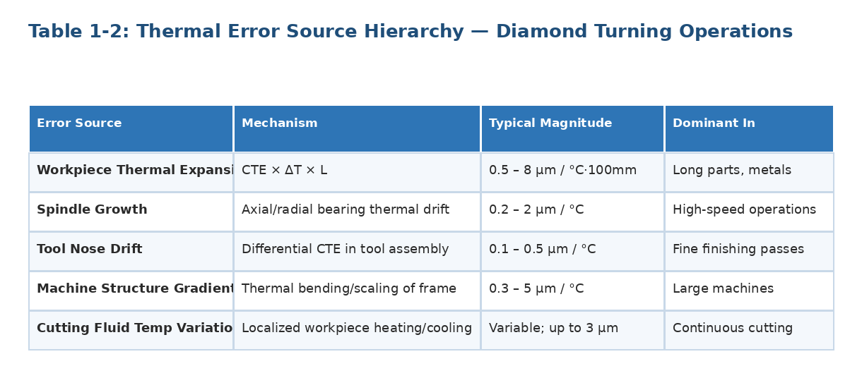
Understanding which error source dominates a given operation guides mitigation strategy. The following characterizes each mechanism:
2. The Cascade from Temperature Variation to Part Rejection
In a production diamond turning environment, temperature variability triggers a predictable error cascade. Ambient temperature swings alter the equilibrium length of the machine structure between the spindle centerline and the tool post.
Simultaneously, the workpiece expands or contracts under the tool, shifting the effective depth of cut. Because the machine's feedback control is position-based rather than thermally corrected, neither the controller nor the operator observes this change in real time.
The resulting artifact is a part whose geometry was correct at the cutting temperature but deviates at inspection temperature. For aluminum optics this can manifest as a measurable power error (defocus) or mid-spatial-frequency ripple superimposed on the desired aspheric form. In semiconductor wafer chucks, the same mechanism produces non-flatness that degrades photolithographic depth of field across the full exposure field.
3. Published Literature
Three peer-reviewed findings establish the quantitative case for active thermal control in diamond turning operations.
Kim and Kim (2003) demonstrated that real-time compensation of spindle thermal growth reduced form error to 0.10 μm P-V on a 100 mm flat aluminum specimen — establishing spindle thermal drift as a principal, directly controllable contributor to form error.
Lee et al. (2011) measured 200–300 nm of thermal deformation induced by ambient air and bearing oil temperature changes alone in an uncontrolled high-precision lathe environment.
Zhang et al. (2021) confirmed in a comprehensive review that multi-layer room temperature control to 20 ± 0.5°C is standard practice for serious diamond turning, and that tighter enclosure control produces further accuracy gains.
The most current synthesis appears in Verma, Ameli, Katiyar et al. (2026), a review in npj Advanced Manufacturing (Nature Publishing Group), which documents that closed-loop servo control, temperature-compensated drives, and active thermal management together enable sustained sub-10 nm form error on optical-grade surfaces across semiconductor, photonic, and quantum optics applications — the same thermal stability requirements that govern all high-tolerance diamond turning work. (DOI: 10.1038/s44334-026-00074-z.)
3.1 Production Yield: Illustrative Model
The yield figures below are a modeled illustration based on published thermal error magnitudes and typical optical mirror tolerance budgets.
For a production run of 50 aluminum off-axis parabolic mirrors with a form error specification of ±50 nm P-V, applying the thermal error ranges from Lee et al. (200–300 nm ambient-induced drift) against a ±2°C uncontrolled environment suggests a large fraction of parts would fail on form error alone before any rework.
In a thermally controlled environment at ±0.01°C, ambient-induced drift falls below the noise floor of the measurement system, and yield is limited by other process variables. At a fully-burdened machine rate of $380/hour with a 3.5-hour mean cut time, even a modest improvement from 25% to 90%+ yield represents a rework cost reduction exceeding $100,000 on a 50-part run.
3.2 Spindle Warm-Up: Published Behavior
The warm-up profile below is representative of aerostatic spindle thermal behavior as documented in the precision engineering literature.
Thermal mapping of representative aerostatic spindles shows a consistent three-phase warm-up pattern: rapid axial growth in the first 20 minutes as bearing preload heat conducts into the shaft (0.15–0.4 μm/min); a decelerating transition zone from roughly 20 to 45 minutes; and a near-equilibrium state beyond 45 minutes where residual drift falls below 5 nm/min under load.
Parts cut during the first 20 minutes routinely show measurable z-axis taper. Standard practice requires a minimum 45-minute warm-up at operating speed under load before any metrology-grade surface is attempted.
4. Specification Requirements and Control Strategy
Specifying temperature control for a diamond turning facility or machine enclosure requires translating part tolerances into allowable thermal budgets. The general approach:
Determine the tightest dimensional or form tolerance on the drawing (e.g., ±0.25 μm radius deviation)
Identify the workpiece CTE and the relevant length scale (e.g., 23.6 ppm/°C, 80 mm optical aperture)
Compute the allowable temperature variation: ΔT = Δdim / (CTE × L) = 0.25 μm / (23.6×10⁻⁶ × 80 mm) = ±0.13°C
Apply a safety factor of 3–5× to account for machine structure drift and spindle contribution, yielding a required enclosure stability of ±0.03–0.04°C
Specify an ATCU capable of ±0.005°C to provide margin for all thermal error contributors simultaneously
Enclosure setpoint should be set to the drawing's nominal inspection temperature (typically 20°C per ISO 1 / ASME B89.6.2) so that a part machined at setpoint will be at correct size when measured on the CMM or interferometer. Coolant supply to the tool post should be temperature-regulated separately, as cutting fluid can differ from ambient by 2–5°C without active conditioning.
Key Takeaway: For any diamond turning application with form tolerances below 100 nm or dimensional tolerances below 1 μm, ambient temperature variation is the single largest controllable source of error. Air temperature ±0.01°C sustained stability is an essential part of the process.
References
Kim, H.S. and Kim, M.S. "Feed-forward control of fast tool servo for real-time correction of spindle error in diamond turning of flat surfaces." International Journal of Machine Tools and Manufacture, Vol. 43, 2003.
Lee, J. et al. "Robust thermal error modeling and compensation for a nano level thermal drift in a high precision lathe." International Journal of Precision Engineering and Manufacturing, Vol. 12, 2011.
Zhang, Z. et al. "Review of geometric error measurement and compensation techniques of ultra-precision machine tools." Light: Advanced Manufacturing, Vol. 2, 2021.
Verma, J., Ameli, N., Katiyar, N.K. et al. "Recent advances in ultra-precision manufacturing of electronic, photonic and quantum devices." npj Advanced Manufacturing, Vol. 3, Article 13, March 2026. DOI: 10.1038/s44334-026-00074-z.